I have tried to provide an accurate account of what I have done. I accept no responsibility for any damage or injury that results from the application of this information. If you decide to follow these instructions, it is your responsibility to verify that they make sense and that you have a satisfactory understanding of electronics beyond what is provided here. I welcome comments and suggestions but regret that I cannot provide assistance with electronic design or assembly.
My 1994 Civic del Sol Si does not have an alarm to remind me that the lights have been left on when I turn off the engine or open the door. I saw an appealingly simple design by Craig Everhart and JP Vossen, which I implemented.
Unfortunately, this design did not work in my car, because the connector which provides +12V when the key is in the accessory or run position is not attached to ground at other times, but instead is an open connection. The factory service manual confirms this. I liked their idea of using the option connectors in the fuse box rather than splicing into wires as others had done. I therefore decided to construct a more complicated version of their circuit that would work in my car.
The under-dash fuse box has five connectors in a row, numbered non-sequentially, as shown in this diagram stolen from JP Vossen (see the above page):
   +-------+-----------------------------------------+
   | +---+ |   +-------------------------+   +------+|
   | |- -| |   |    Big wiring harness   |   |      ||
+--| |- -| |   |        connector        |   | |  | ||--+
|  | +---+ |   +-------------------------+   |      ||  |
|()| _____ +---------------------------------|  --  ||()|
|  |(- - -)   ( - ) ( - ) ( - ) ( - ) ( - )  |      ||  |
+--| -----      5     4     1     2     3    +------+|--+
   |-------------------------------------------------+

   |                                                 |
   |            { Here There Be Fuses }              |
   |                                                 |
The connectors are as follows in a 1994 Civic del Sol (verified with the service manual):
| Connector | Description |
| 5 | +12V constant |
| 4 | no connection (US models) +12V constant (Canada)? |
| 1 | +12V if ignition on |
| 2 | +12V if lights on (#19 fuse) |
| 3 | +12V if accessories on |
I determined experimentally that a ground was available at the middle prong of the 3-prong connector which is just left of the five connectors described above.

When the headlamps or parking lights are on, the connector labeled "Lights +12V" has battery voltage. If the key is in the "Accessory" or "Run" position, the connector labeled "ACC +12V" has battery voltage, and transistor Q1 provides a path to ground. This ties the base of Q2 to ground, and hence no current can flow to the buzzer. The resistors limit the current draw to well under 1 mA; their values are not critical and they need not be identical. Likewise, other NPN transistors and buzzers may be substituted provided their specifications allow 12-15 VDC operation.
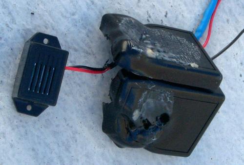
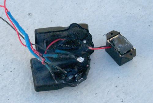
I found a nice little enclosure at Mar-Vac Electronics with inside dimensions of about 1.00 x 1.75 x 0.25 inch. No matching proto board was available, so I just soldered all the parts to each other directly, using heat-shrink tubing on all of the leads to ensure that they would not short against each other. I made the wires to the fuse box about 6 inches long, and mounted the box to a concealed surface of the dashboard using Velcro.
Before assembling the circuit in its final version, I strongly recommend prototyping it on a breadboard and using a laboratory power supply with a current limiter. The bench equipment can cope with shorts more gracefully than your automobile!
A reminder to novice heat-shrinkers: You need to put the tubing on the wire before putting big things on both ends of the wire. I speak from experience...
The loudness of the buzzer that I used fluctuates with the supplied voltage. Unfortunately, the supplied voltage fluctuates quite a bit when the engine stops, which is when the buzzer normally sounds. The result is an unpleasant warbling. I may solve this problem by adding, say, a 5V voltage regulator before the buzzer and using a 5V buzzer instead.
The parts listed here are what I actually used, but you have considerable latitude to substitute (see above). I purchased them at the Mar-Vac Electronics store in Pasadena, CA.
| Component | Description |
| R1, R2 | 50 kOhm; 1/2 watt |
| Q1, Q2 | MPSA13 Darlington NPN transistor V(BR)CES = 30V |
| Buzzer | 12 VDC, 15 mA |
| Connectors (ACC, Lights, GND) | 16-14 GA .250 quick slide female |
In March 2003, I added a resistor R3 (5 kOhm) between the Accessory input and ground. This resistor was necessary because a CD receiver that I installed leaks a small amount of power to the Accessory circuit when the circuit should be unpowered. This leakage prevented the buzzer circuit from functioning.
Alas, when reassebling the case, I apparently created a short circuit by stripping a couple of wires with the case's screw. My next trip to work was a smelly one:
|
|
|
|
The good news is that before it melted, the circuit worked properly, indicating that adding the resistor solved the problem.
I have rebuilt, with a slightly modified design and improved enclosure.